A hot shop is a system — gas, air, power, heat, exhaust, and the controls that tie
it together. Documenting yours as a scene sketch, an electrical one-line, a piping
& instrumentation (P&ID) diagram, and a bill of materials with real
part numbers makes it far easier to fix, order, insure, and teach. You
don't draw any of it by hand: describe your shop to an AI and have it render the
diagrams and the parts list. Then publish it here so the next person can find the
part in one search.
Safety first. These are schematic documentation,
not engineering drawings. Gas and high-current electrical work must be designed,
installed, and inspected by licensed professionals to your local code. Mark
anything uncertain as TBD — the examples do.
Generated from a plain-language description (below). Schematic, not to scale;
unknown pressures/ampacities marked TBD.
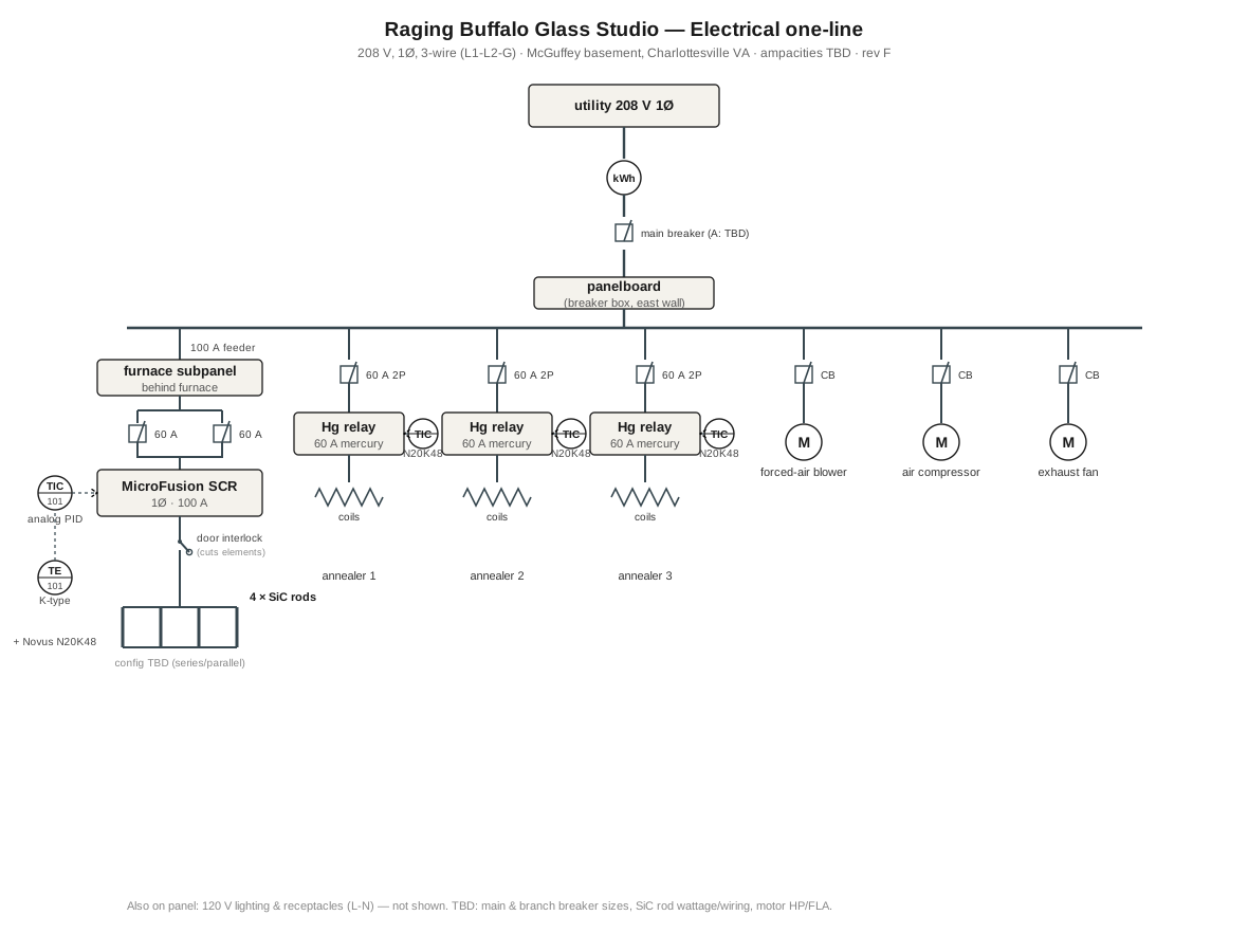
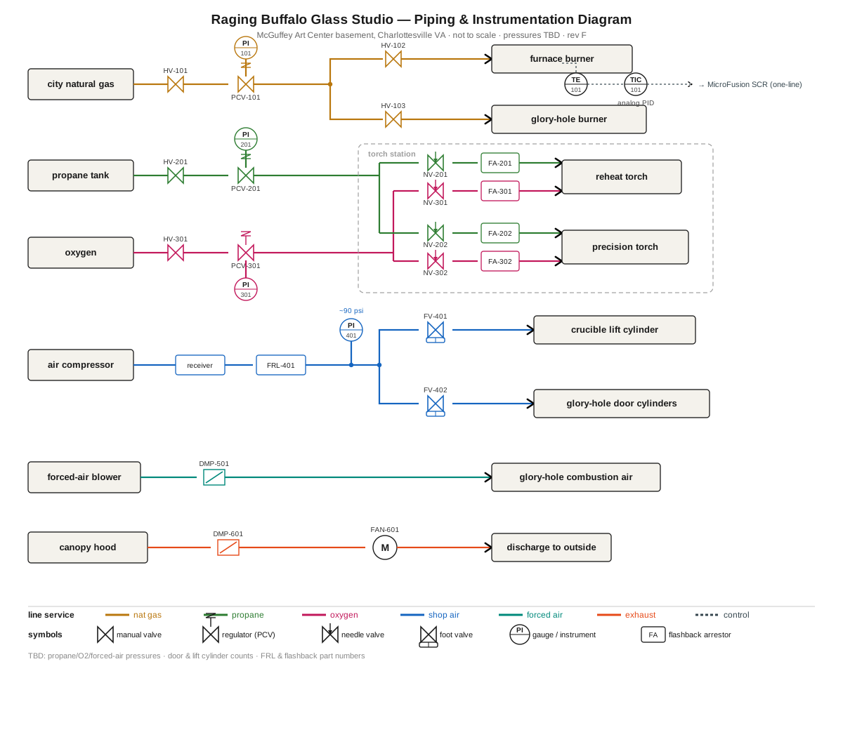
Electrical one-line — service → panel → annealers + furnace (SCR → SiC).P&ID — gas / air / exhaust with valves, regulators, and instruments.
Prompts to get you started
Copy a prompt, fill in the bracketed parts for your shop, and paste it into your
AI of choice. Start with the scene, then the diagrams, then the parts list.
1 · Describe the spaceDraw a schematic top-down floor plan (not to scale) of my glass studio. The space is [24 × 24 ft]. The glory hole is in [one corner], with forced/combustion air along [the back wall] from a [squirrel-cage blower] in [a closet outside], plus [natural gas from the city]. The furnace is [to the right of the glory hole], with [4 × SiC elements] wired through breakers to an [SCR] controlled by a [Novus PID] with a [K-type thermocouple]; [160 lb] crucible; crucible access via a [pneumatic lift] fed by [a small quiet compressor in the opposite corner]. To the right are [three annealers: a 40″ coil unit on a 60 A breaker and two Paragons on 60 A breakers with mercury 60 A relays, all on one Novus controller]. Ventilation above the hot equipment is a [large exhaust motor behind the utility wall]. The bench is [between glory hole and furnace, facing the equipment]; the marver is [3′×2′, ~5′ right of the bench]; viewing area [~8′ back at the wall]. Label each device; show gas / air / power / exhaust in different colors; mark unknowns TBD. Output one clean SVG.
2 · Electrical one-lineFrom the scene above, produce an electrical one-line diagram as an SVG: service and main breaker, panelboard, each annealer branch (breaker → mercury contactor → coils), and the furnace feeder ([100 A] feeder → subpanel → two [60 A] breakers → SCR → door interlock → SiC elements). Put amperages on each run; label unknown ampacities/wire sizes as "TBD, verify with an electrician." Include a legend.
3 · Piping & instrumentation (P&ID)Produce a P&ID as an SVG for the fuel/air/exhaust systems: natural gas (city → meter → regulator → shutoff → glory hole & furnace burners), propane and oxygen if present (tanks → regulators → torch station), compressed air, combustion/forced air (blower → burners), and exhaust (hoods → duct → exhaust motor → outside). Use valve/regulator/instrument symbols; color each medium; mark pressures TBD where unknown; include a legend.
4 · Bill of materials (real part numbers)Build a bill of materials table with columns: System · Component · Manufacturer · Part number · Spec · Where to buy · Notes. Include controls (PID, SCR, thermocouples, relays/contactors), heating elements, blowers/motors, gas regulators and valves, and safety interlocks. Use the REAL manufacturer part numbers I give you (read off the nameplates); where I don't have one, leave it blank and note what to check. Do not invent part numbers.
Got a description, diagrams, and a BOM? Add them under
Explore → Add to the database → Shop.
Everything is reviewed before it appears; contact details stay private. The goal is
a shared, open library of how glass shops are actually built.